35mm Narrow Glide Fork Brace

1986 fxrd narrow glide fork brace

I’ve been interested in fork brace for 35mm Showa Narrow Glide Forks for a long time. This time, I accidentally acquired an aluminum fender for 19 inch tyres. So I decided to make a fender support bracket which can also be used as a front fork stabilizer.

harley-davidson 35mm narrow fork brace

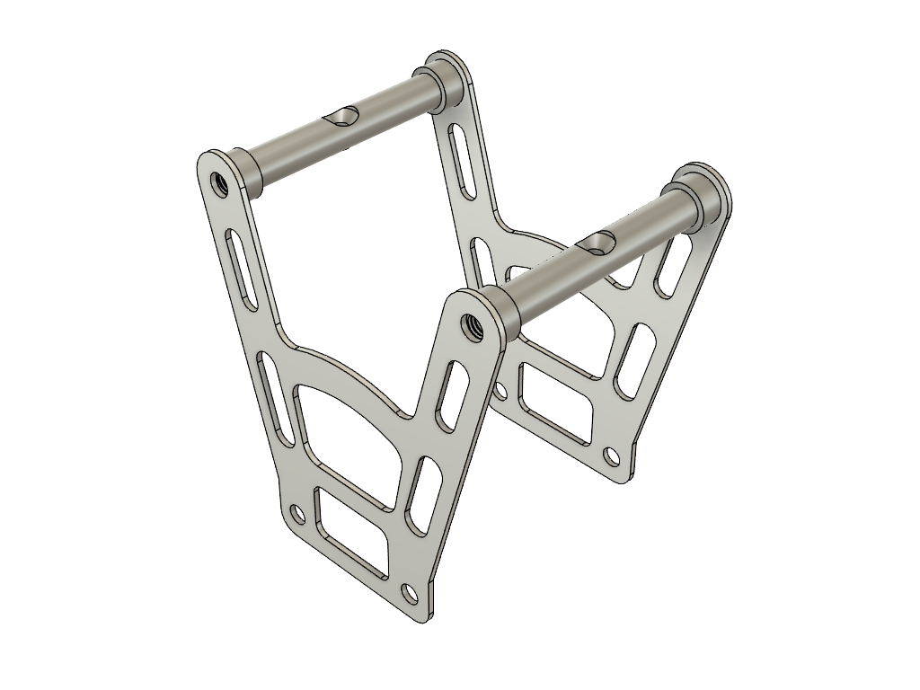
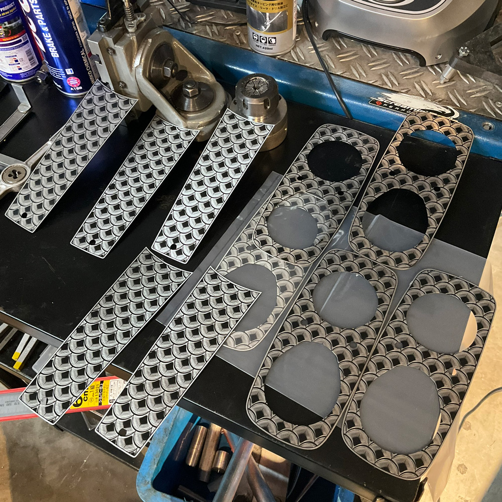
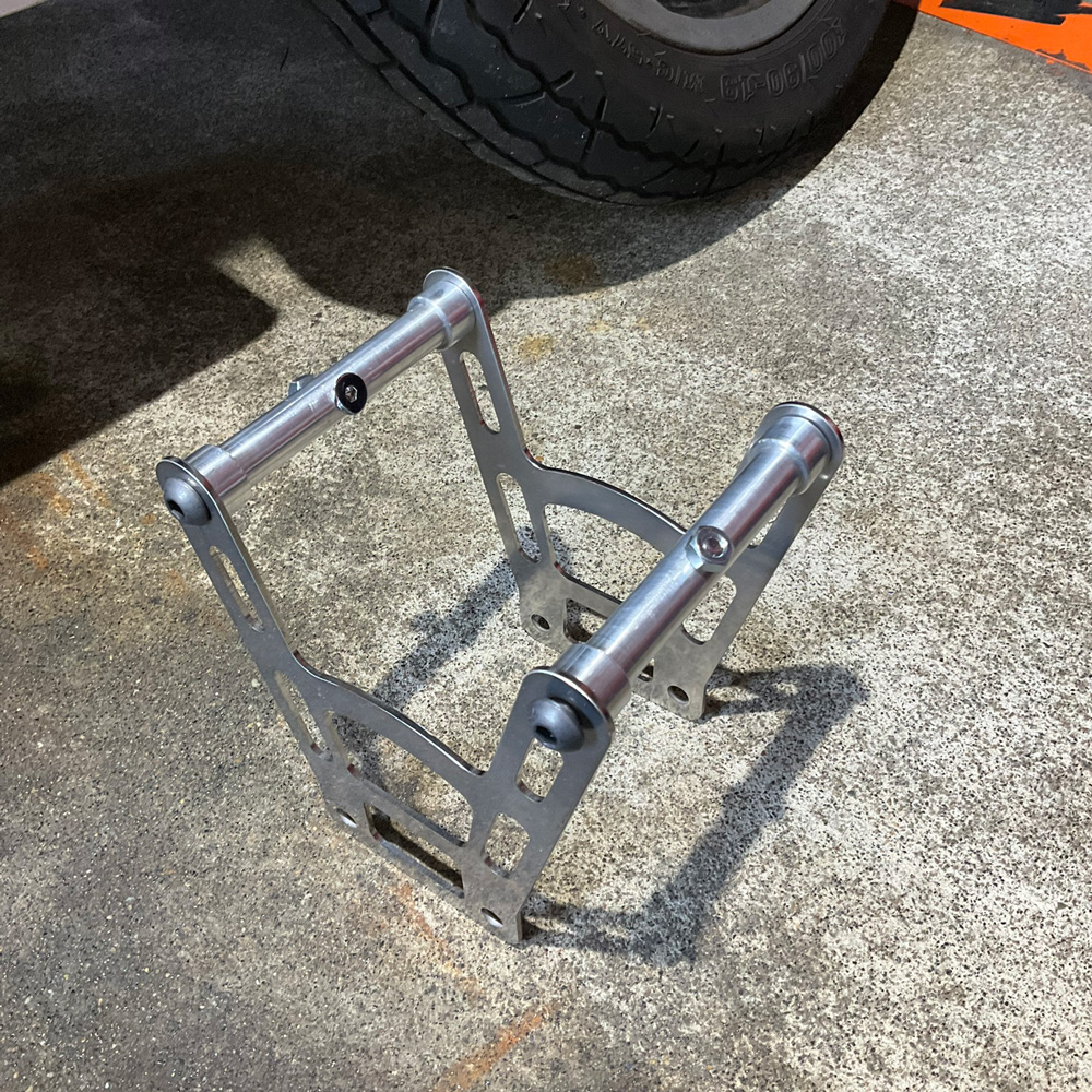
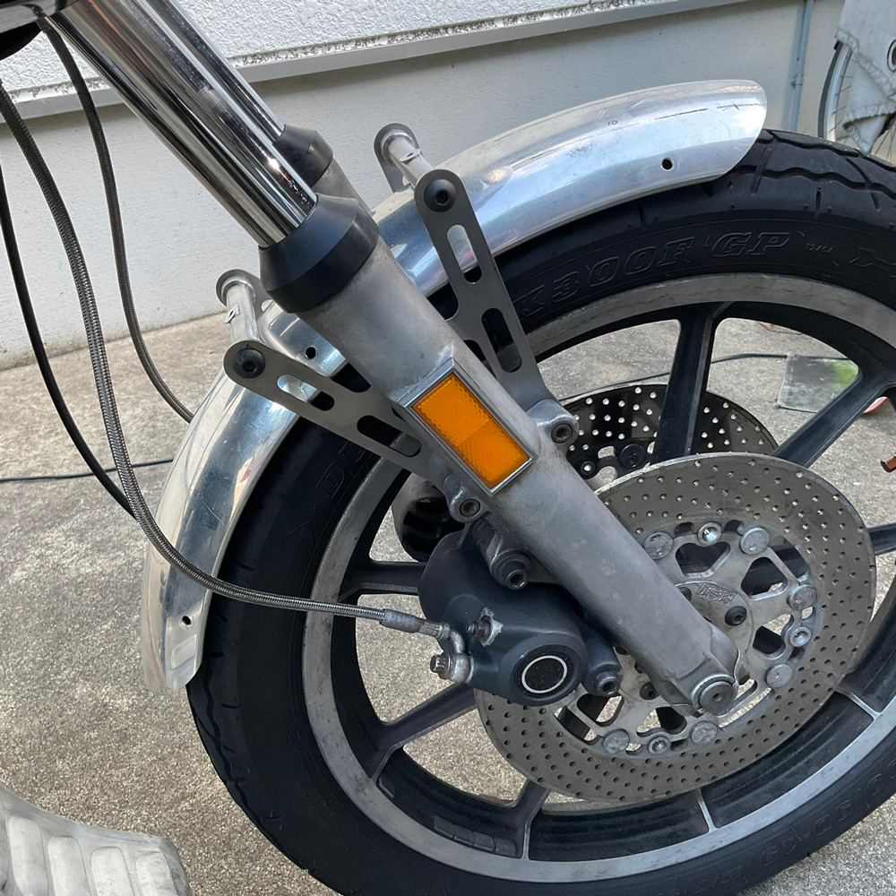
As narrow glide forks literally don’t have much more space than necessary between both fork tubes, considering the strength of the parts, I tried to go with a 2.3mm thickness stainless steel plate as main body instead of aluminum plates.

harley davidson narrow glide fork brace

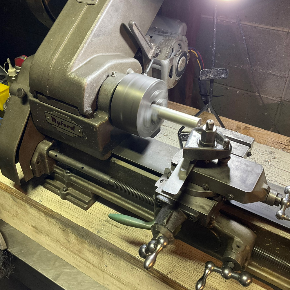
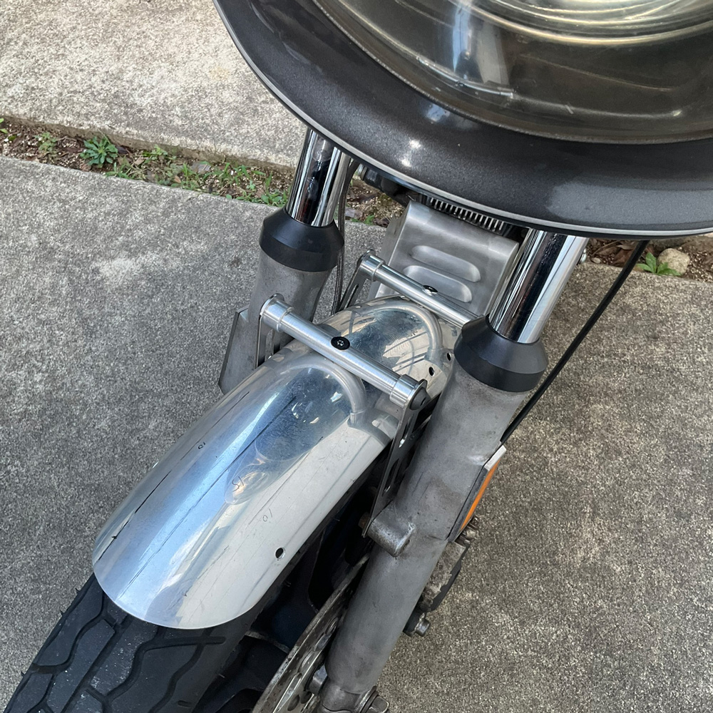
I made two aluminum rods which would bridge both stainless steel plates. The material of the rods are aluminum alloy 6061.

harley davidson narrow glide fork brace

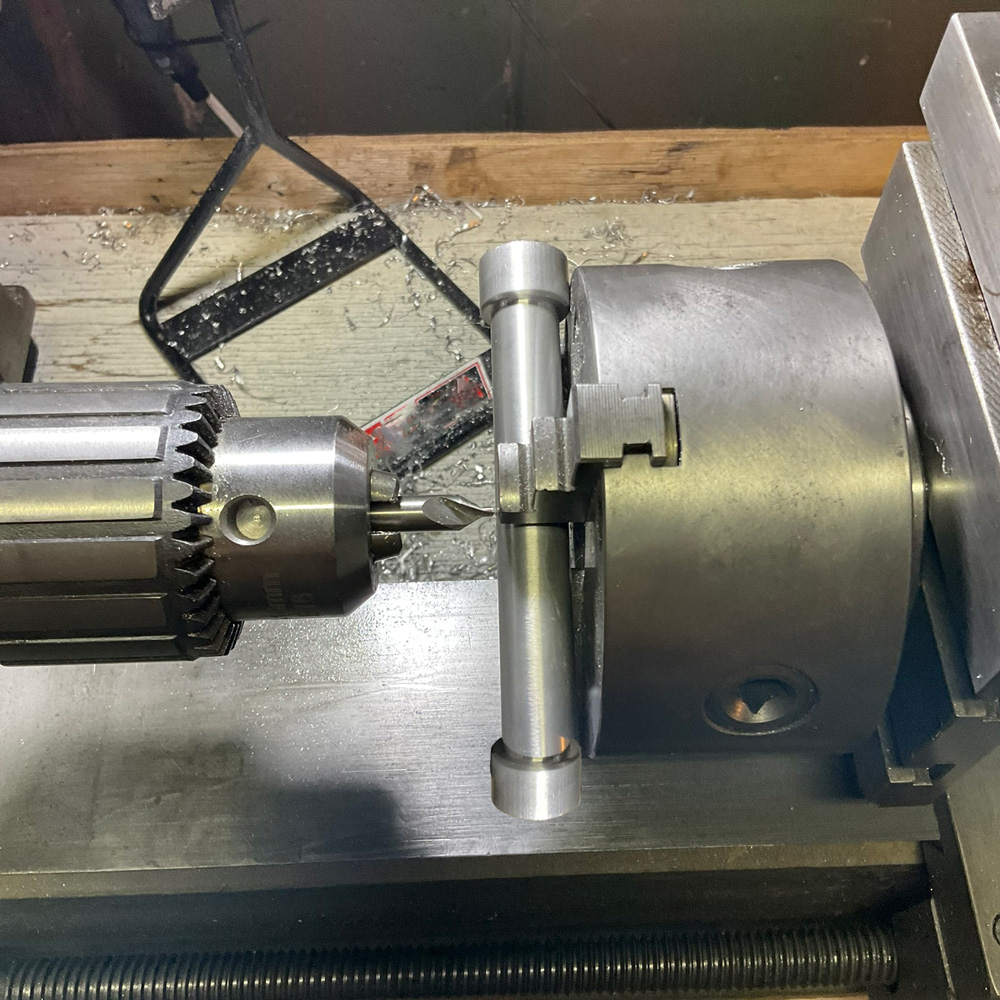
I drilled to make a hole on the center of each rod to put through a screw to hold fender.

Harley Davidson 35mm narrow glide fork brace

This is the aluminum fender which I acquired not long ago. I suppose it was a fender for Yamaha SR400 which was equipped with 19 inch front tyre like Harley-Davidson FXR models.

1986 fxrd narrow glide fork brace

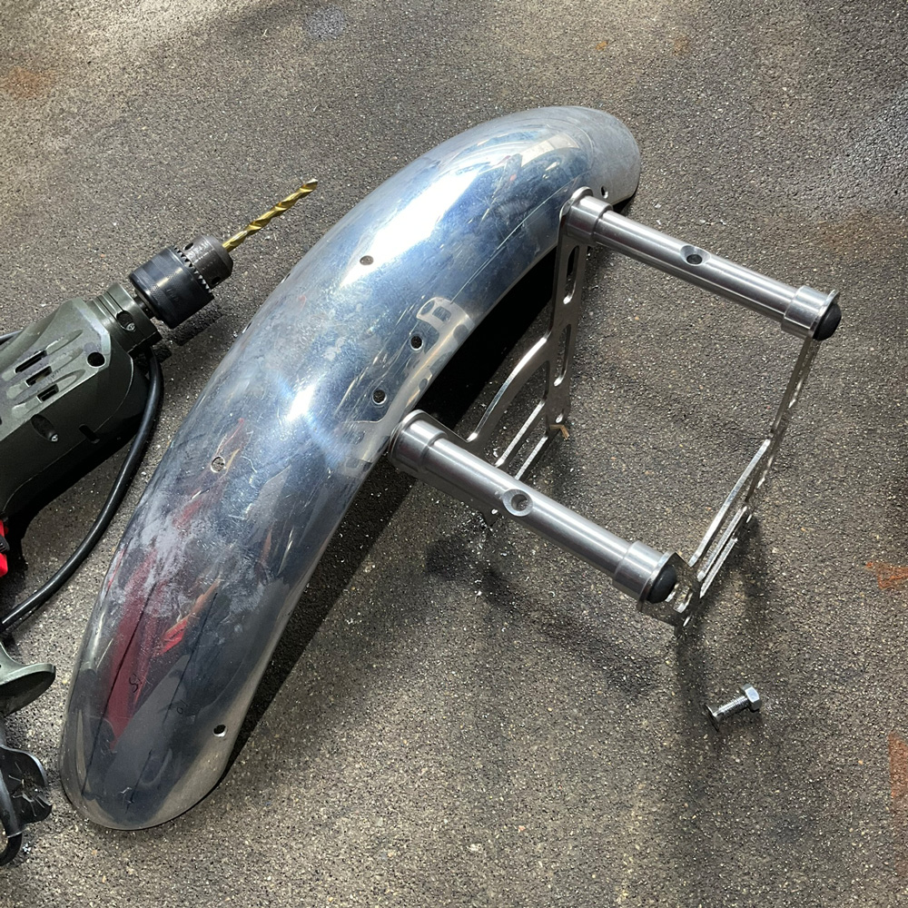
I drilled two holes on the center of the fender for screws. Regrettably, several holes are remaining on either side of the fender which have been used on SR400. I must weld and fill them in the future.

1986 fxrd narrow glide fork brace

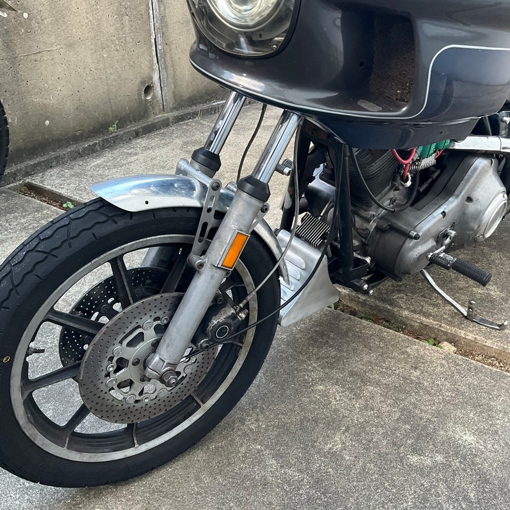
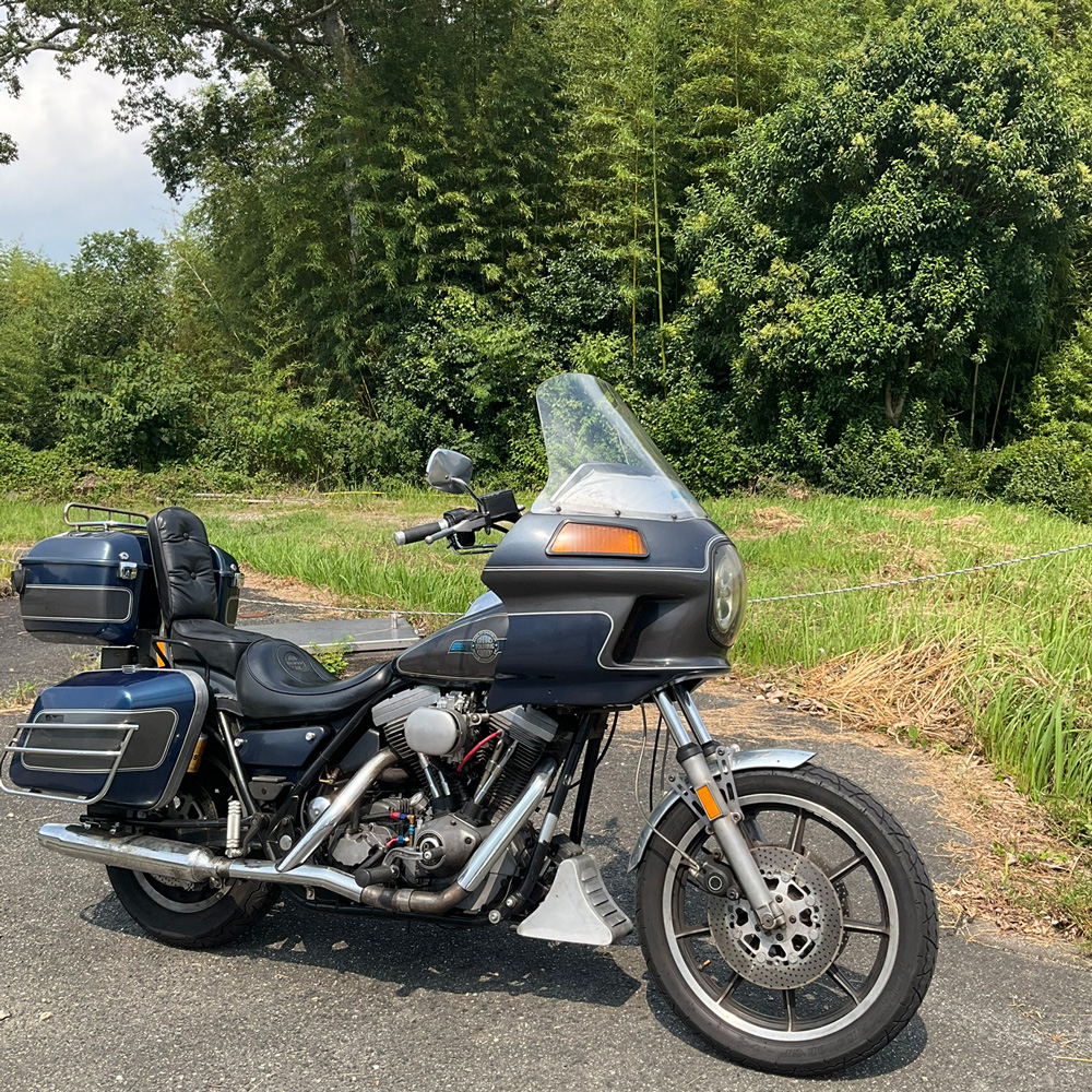
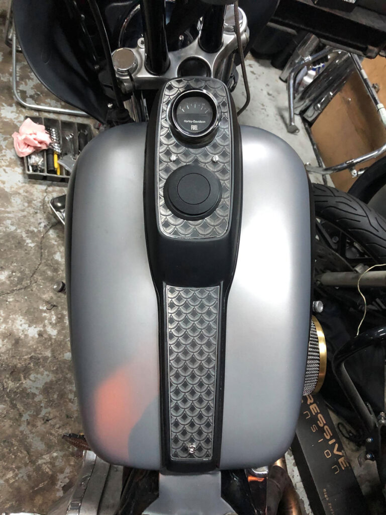
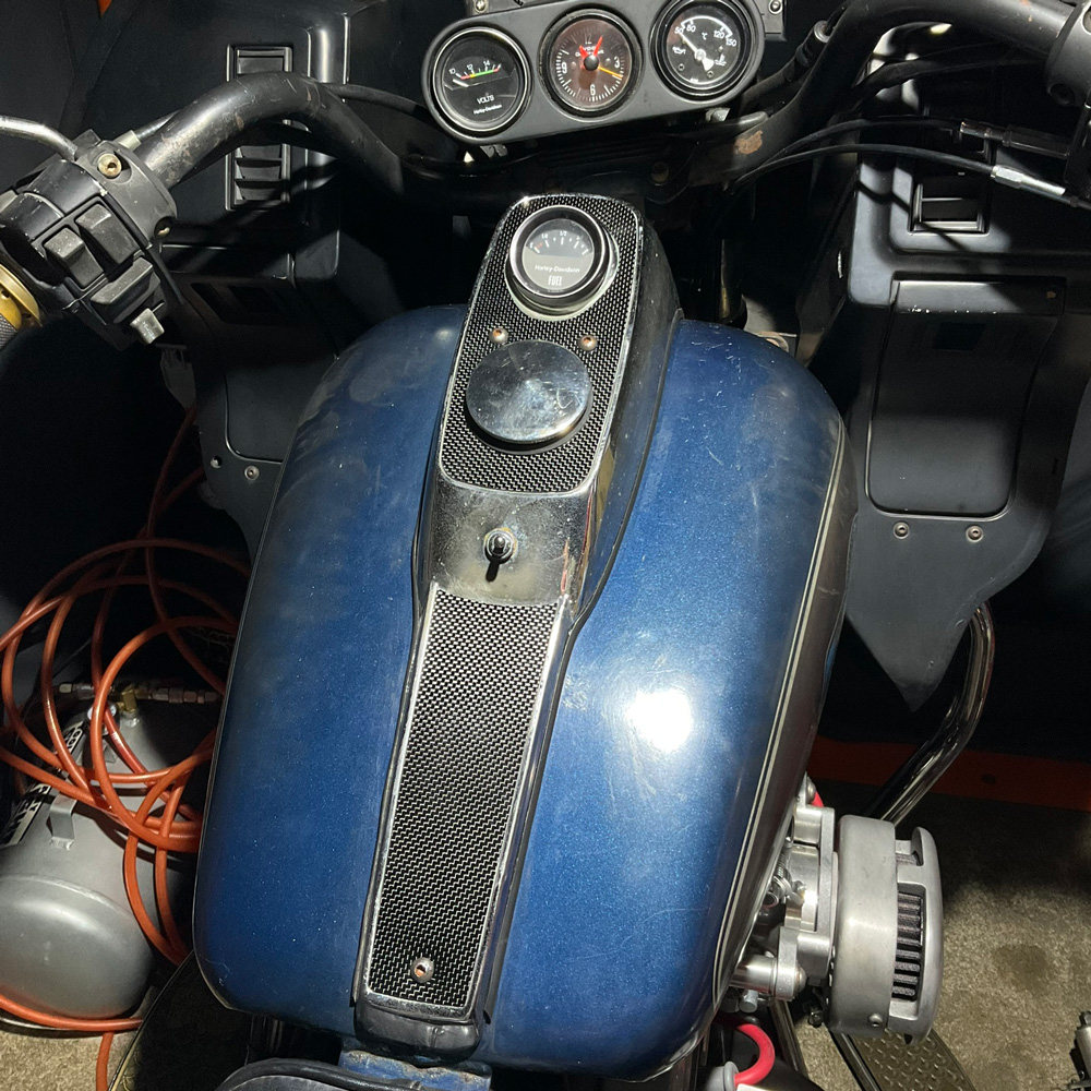
Finally, I put them on my FXRD. It seems that nothing could be a trouble. There is enough clearance between the bracket, fender and tyre.

1986 fxrd narrow glide fork brace

1986 fxrd narrow glide fork brace

At last, I’ve done test riding and checked how it worked.

I could feel slightly that the bracket stabilized wobbling of the forks especially turning right or left.

I’m going to continue test riding for a while since I think there are several critical elements demanding for motorcycle parts and durability is one of the most important elements of them all.

harley davidson 1986 fxrd with fork brace

The failure of Altmann AMM-P2 ignition module

altmann amm-p2 ignition module

altmann ignition sensor plate

Symptom
Engine was stopped suddenly on the highway and couldn’t restart. No fire was identified on the rear spark plug.
Cause of failure
Ignition system
Background
Shortly before engine stopped, the following symptoms sometimes occurred.

-Engine speed can’t increase smoothly above 3,000 rpm.
-At 2,800 rpm or less, engine operates normally.

Parts

Cam position sensor, Ignition module:Altmann Micro Machines

Comment

The cam position sensor seemed to operate normally. So I assumed that the ignition module might be wrong.
I told the symptom to Charles Altmann (Altmann Micro Machines) by email and asked possibility of failure of his product.
Soon I got a reply from him.
He advised me to take a sniff of the module box. I did it and found the module box smelled bad.
He gently explained me the situation.
The high voltage current passing through the plug code always seeks and finds the place to discharge. Sometimes cylinder fins or wire harnesses around ignition coils could be the place.
This time, the high voltage current leaked from plug code discharged to the wire harness and it flooded into the ignition module.
As a result, the transistor in the ignition module was burnt.
A burnt transistor stinks.

altmann amm-p2 ignition module

I sent him some pictures that of around ignition coils.
He looked at them and told me that the clearance between plug codes and signal cables connected to the ignition module was too close. It should be wider to avoid unexpected discharging.

He also mentioned that the dual plug setup is not recommended because the second plug code is located between two push rods and the clearance between the plug code and push rod covers is so close.
This causes unexpected discharging easily.
There is another risk we should accept when running with dual plugs.
The high voltage current flows from the ignition coil to the first plug and then to the second plug via engine itself and returns to the coil following the same path.
Dyantek coil forms electric loop and these elements are connected each other with single road.
It means that the failure of one of these elements is the complete failure of the whole ignition system.

dynatek green coil dual fire

I understood what Mr. Altmann said in his email, however, I didn’t give up dual plugs.
I put Dyna-2000i into my FXR instead of AMM-P2 to get back on the road.
AMM-P2 has some good points. 3 rotary switches located on the side of ignition module box are ones of them. We can change ignition map easily and whenever we want even when we are running on the road. Someday in the future, I may try AMM-P2 again.

dynatek dyna2000i